Choosing grippers for bin picking starts with the contact between the tool and the part. Can a cup seal, can a magnet hold through the available thickness, or can fingers enter a bore without hitting a neighbour? Those answers determine the gripping principle before a catalogue or brand shortlist becomes useful.
This guide compares vacuum, magnetic, finger, soft and hybrid end-of-arm tooling, then works through holding force, reach and the failures that stop a bin picking cell from clearing its container. The practical output is a tool specification: where it grips, how much clearance it needs, and how it keeps the part stable on the way to its destination.
Disclaimer: we do not sell grippers. Our AI Vision System works with any robot, PLC and end-of-arm tooling, so we have nothing to defend in this comparison.
What a bin changes
If you have automated pick and place before, most of what you know still applies. Five things change once the parts are loose in a container, and they drive most of the design.
The tool has to work inside a box, so anything on it wider than the part becomes a collision risk. The approach angle is no longer yours to choose, because parts land as they land, and a tool that only works straight down onto a surface loses every part lying at an angle. The target has neighbours, which block access and can be dragged out with it. Parts interlock, so a grasp that looks correct can still lift two. And the bin empties as you work, so the first pick and the last happen at different depths, with different reach and different lighting.
Everything below follows from those five.
Start with the part
Before you look at any catalogue, answer six questions about the part itself. All of them can be settled with the part in your hand and a drawing.
Is there a sealable area? A vacuum cup needs a continuous, reasonably smooth patch at least as large as the cup, on a face that will be accessible while the part is in the bin. Through-holes, porosity, deep texture and ribbing all remove that patch.
Is the part ferromagnetic? Do not assume that steel means magnetic. Goudsmit publishes relative holding efficiency of 100 percent for low-carbon steel, 70 to 80 percent for high-carbon alloys, 60 to 75 percent for ferritic stainless, 1 to 3 percent for austenitic stainless, and zero for aluminium and copper. Austenitic stainless is common and effectively non-magnetic, so confirm the grade.
How thick is it? This matters only if you are considering a magnet, and it is a hard physical limit rather than something you can tune later. See de-stack thickness below.
Is there a bore or a clampable feature, with clearance around it? Fingers need both. The clearance is the part first-time projects tend to overlook, because a feature that is easy to grip on a bench can be unreachable when the part is surrounded by others.
How is the part contaminated? Oil does not break a vacuum seal, it reduces friction, which matters on any pick that is not straight up. Schmalz publishes a friction coefficient of 0.5 for dry metal against 0.1 to 0.3 for oiled surfaces with standard cups.
Where does the part go afterwards? A part dropped into a tote tolerates several millimetres of error. A part loaded into a fixture may tolerate less than one, and any movement the tool allows while the part is in hand adds to that error.
Those answers usually resolve in a fixed order. If there is a sealable face, start with suction, because it is simpler, faster and more tolerant of vision error than anything else here. If not, and the part is ferrous and thick enough, use a magnet, which is unaffected by holes, oil and rough finishes. If neither applies, use fingers, and prefer a grasp that expands inside a hole rather than closing around the outside. If different parts in the same bin need different answers, you are looking at a hybrid tool or a quick-change arrangement.
What each principle holds
Vacuum works by evacuating a cup against the part so that atmospheric pressure holds it. Flat cups resist sideways loads and evacuate quickly, which suits smooth faces and short cycles. Bellows cups, which have a concertina profile, conform to curved or uneven faces and suit fragile parts and moulded plastic parts, and they typically give 10 to 20 mm of compression travel. Cups built for this job are small: Schmalz's Bin-Picker SBPG holds 20 N at minus 600 mbar, which is 0.52 to 0.72 kg depending on how the load is applied.
A through-hole under the cup does not necessarily end the pick, but it changes the problem. A sealed cup needs airflow only to evacuate and then holds; a leaking cup needs flow continuously, so the vacuum generator has to be sized against the leak rate rather than against the vacuum level. Robotiq states plainly that its EPick is not recommended for porous material for exactly this reason, since its integrated pump would run continuously to compensate, and Piab's piGRIP FXI lip is made for heavily perforated surfaces. One component to specify from the start: a vacuum switch on the tool. Without one, a failed pick is indistinguishable from a successful one until the part fails to arrive.
Magnets hold ferrous parts through contact on a single face, which covers a set of cases where a cup cannot seal at all. Published holding forces cover a wide range, from 118 N at 0.2 kg for Magswitch's D12 up to 12,795 N at 31 kg for its AR110. Switchable permanent magnets redirect the magnetic flux mechanically or pneumatically and hold with no power applied, so a power failure does not release the part. Electro-permanent magnets switch with a pulse of current and then hold unpowered, at 530 N and 300 ms for SCHUNK's EMH-RP 036-B and 350 ms for Goudsmit's E-gripper.
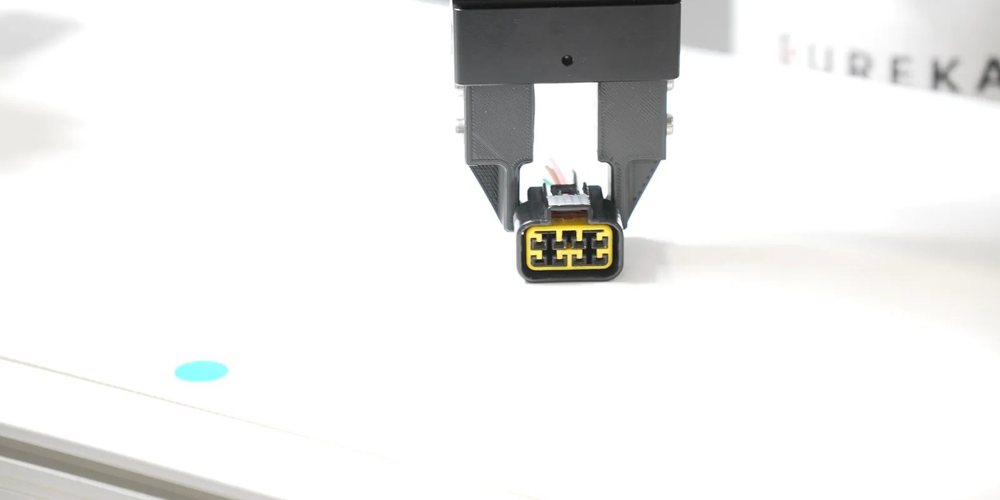
Two-finger parallel grippers close two jaws on the outside of a feature or expand them inside a bore, and they are the most mechanically robust finger design available. Prefer the internal grasp where the part allows one, because expanding inside a bore collides less with neighbouring parts and self-centres the part as it closes, which improves placement accuracy. A through-hole that prevents a vacuum pick is often the best gripping feature on the part. Finger geometry is your main design variable here, since standard finger blanks are meant to be replaced. Tapering the last few millimetres of the tips to a point lets them enter the gap between parts rather than pushing the neighbours aside.
Three-finger centric grippers close three jaws on a common centre, which self-centres round and hexagonal parts and suits shafts and billets going into a chuck. They are larger than a two-finger design, and size limits access in a bin. Published bin picking guidance on them is thin, so treat this as something to evaluate rather than an established practice.
Soft and adaptive grippers conform to irregular shapes and are used mainly in food and produce handling. The payload rating usually settles the question before a trial does, since Piab's piSOFTGRIP is rated at 150 g in size 50 and 250 g in size 100. Their compliance also leaves the part's position in the gripper less certain, which costs you accuracy at the destination.
Needle grippers drive fine pins into textiles, foam and preforms, and mark the material by design. We found no documented deployment in random bin picking, so treat it as unproven ground.
Hybrid tools combine two principles in one head, and they exist because a single principle tends to clear most of a bin and then stall on the remainder. The mechanism is worth understanding early: a part lying flat in the open is a suction pick, the same part wedged against a wall with only an edge exposed is a finger pick, and a tool that can do both keeps working through the awkward parts at the bottom and in the corners. Commercial versions include Goudsmit's MagVacu, which pairs a magnet with a vacuum cup so that one head covers perforated ferrous sheet and non-magnetic grades, and Zimmer's multi-item gripper, which pairs a mechanical gripper with a vacuum gripper and is rated for workpieces of 120 to 255 mm up to 5 kg. Tools can also be built. On one application with a complex metal part we combined two gripping principles in a single custom tool because no standard gripper handled every presentation, and 3D printing has reduced the cost of that route considerably.
| Type | Suits | Fails on | Bin-specific risk |
|---|---|---|---|
| Vacuum, flat cup | Flat, smooth, clean faces; fast cycles | Through-holes, porosity, heavy texture, oil | Releases the load on air or power loss |
| Vacuum, bellows cup | Curved or uneven faces, fragile and moulded parts | Same as flat cups, plus high shear loads | Part swings under acceleration |
| Magnetic, switchable permanent | Ferrous parts with holes, oil, rust or rough finish | Austenitic stainless, aluminium, copper | Double picks below the de-stack thickness |
| Magnetic, electro-permanent | Same, where electrical control is wanted | Same | Duty cycle caps pick rate |
| Two-finger parallel | Parts with a bore or a clampable feature | Flat parts lying with no accessible side | Needs clearance on two sides; collides with neighbours |
| Three-finger centric | Round and hexagonal parts going into a chuck | Non-symmetric geometry | Size limits access in a deep bin |
| Soft and adaptive | Delicate and highly variable items, food and produce | Industrial payloads | In-hand pose uncertain, so placement suffers |
| Needle | Textiles, foam, preforms, insulation | Rigid parts, and it marks the material by design | Unproven in random bins |
| Hybrid, fingers plus suction | Bins where the same part presents several ways | Narrow deep bins, because of the added size | Larger tool reduces reach and corner access |
Sizing the tool
Holding force for a vacuum cup is the pressure difference multiplied by the effective area of the cup. The figure you actually need depends on how the load is applied, which is why Schmalz publishes three load cases. A horizontal cup lifting vertically needs m times (g plus a) times the safety factor. A horizontal cup with the load applied sideways needs m times (g plus a divided by the friction coefficient) times the safety factor. A vertical cup needs m divided by the friction coefficient, times (g plus a), times the safety factor. The friction coefficient is the term most often estimated wrongly on a first project, which is why the contamination question above matters more than it looks.
Safety factor is the margin you apply on top of that calculation. Schmalz sets a minimum of 1.5 for smooth, dense parts, which the German accident prevention regulations make binding, rising to 2.0 or more for porous, rough or oiled parts and 2.5 or more where the part is swivelled during handling, which bin picking normally does. Its worked example gives you a sense of scale: a 61.33 kg steel sheet accelerating at 5 m/s², friction 0.5, safety factor 1.5, needs 1,822 N. Magnet vendors apply the same principle in reverse, with Magswitch requiring a 5 to 1 factor against laboratory figures measured on 2 inch SAE1018 steel with optimised pole shoes. EN 13155 is the standard covering both vacuum lifters and lifting magnets, and worth having to hand when you write the specification.
Stroke and grip force are the two numbers on a finger gripper datasheet, and they scale together by frame size rather than independently, so you cannot simply buy more force at the same opening. SCHUNK's EGP series runs 6 mm of stroke at 140 N on the EGP 40, 8 mm at 210 N on the EGP 60 and 10 mm at 300 N on the EGP 64. The EGK series covers 26.5 mm at 20 to 50 N and 41.5 mm at 55 to 150 N, and the EGU series reaches 60 mm and 1,950 N. Robotiq's 2F-85 offers 85 mm of stroke, 20 to 235 N, 5 kg payload and 0.05 mm repeatability. Size the stroke against your part's tolerance band plus the clearance you need on approach, not against its nominal width.
De-stack thickness is the minimum part thickness at which a magnet lifts one part rather than two. A magnet strong enough to hold your part through its own thickness will also reach the part beneath it unless that thickness attenuates the field enough. Magswitch publishes 1.5 mm for the D12, 12.7 mm for the AR70 and 38.1 mm for the AR110. If your parts are thinner than the figure for the force you need, plan a separation strategy or choose a different principle, because this is not something tuning will fix.
Compliance is the travel the tool gives along the approach direction, through a bellows or a spring, and on a vision-guided cell it functions as error budget. Work it through with a cup that extends 220 mm and compresses by 20 mm. Set the tool centre point, the reference point the robot actually drives to, at 210 mm rather than 220. That puts the robot 10 mm into the compression at nominal, so the tool absorbs plus or minus 10 mm of error in the approach direction, which is 10 mm of combined vision, calibration and robot error you no longer have to eliminate elsewhere.
Designing it to reach into the bin
Holding the part and reaching it are separate problems. Force sizing covers the first. Geometry covers the second, and it is where first projects most often need a second iteration of the tool.
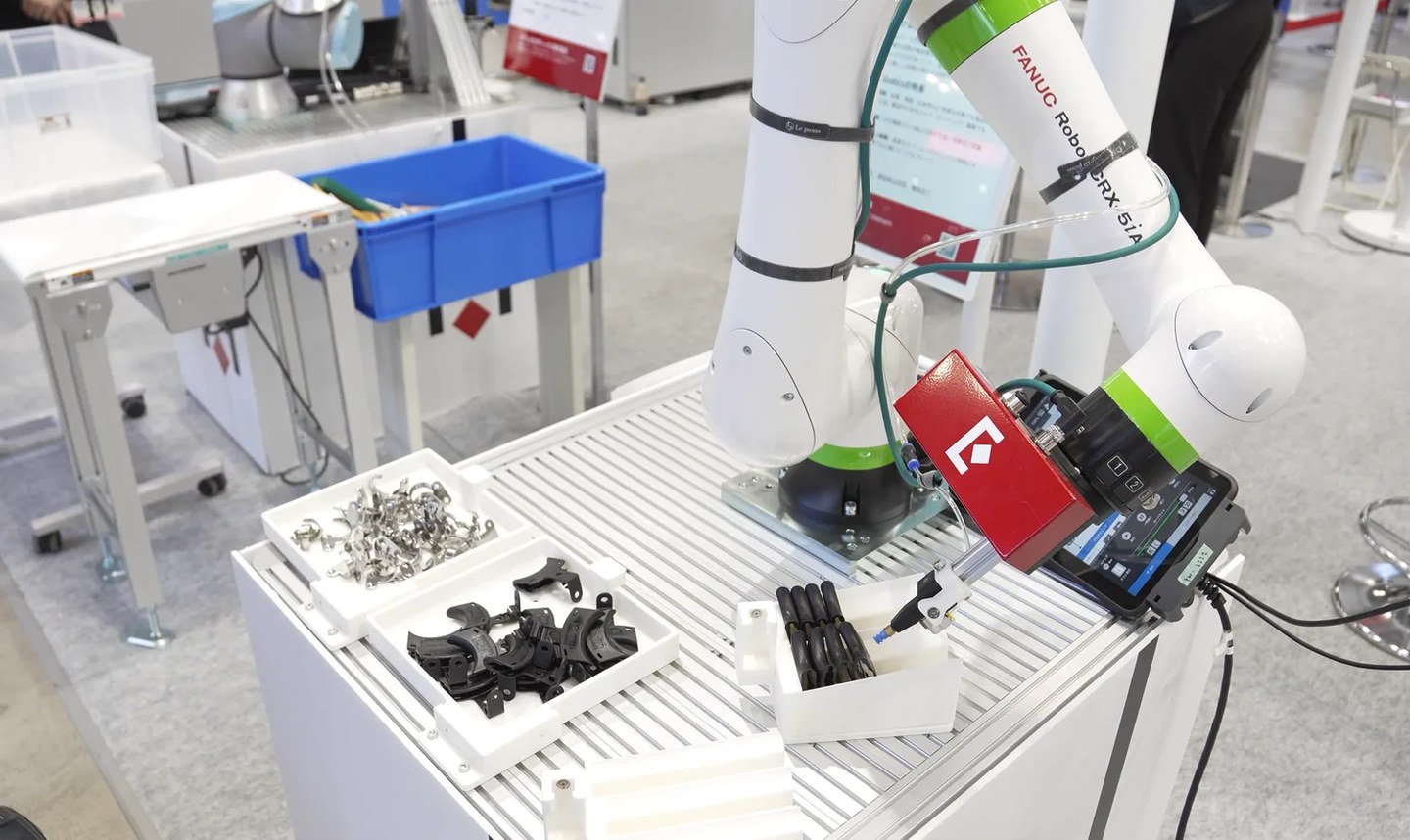
Keep the part of the tool that enters the bin as small as possible, with bulky elements kept up near the robot flange and a slender element reaching down to the tip. Ideally the flange never enters the bin at all. Make that slender section about as long as the bin is deep, and keep it rigid, because deflection at the tip is an error your calibration cannot detect or correct. Design for angled picks, since a tool that tolerates deviation from the nominal orientation gives you more pickable parts, and a continuous tilt range is more useful than a fixed slant angle. Route connectors out of the top of the tool where you can and use L-shaped fittings where they have to exit sideways, because snagged hoses are a common cause of unplanned downtime.
Offsetting the tool sideways from the flange axis helps you reach into bin corners and avoid wrist singularities, the configurations where two robot axes line up and the arm loses a degree of freedom. It costs payload, because robot ratings assume the load sits at or near the flange axis and the moment at the wrist grows with the offset, so check the figure against your robot's payload and centre of gravity chart rather than against its nominal rating. Geometry adds a second constraint: rotating the sixth axis through 180 degrees sweeps a circle of twice the offset radius, which can put the outer picks beyond reach. Where one tool cannot cover everything, several grippers on a quick-change coupling usually beat one oversized head, since a larger tool reduces reach and corner access.
What goes wrong in production
These are the failures that do not appear in a demo and do appear in week three.
Double picks. Magnetic ones have the physical limit described above. Suction ones happen with nested or stacked parts. In both cases the answer is detection rather than prevention, through vacuum level, gripper position feedback, a weight check or a sensor downstream.
Entanglement. Hooks, springs and open rings interlock, and the grasp can be correct while the lift brings up two parts. The documented remedies are unsophisticated and effective: put the part down and pick it up again in a better position, or agitate the bin so the parts resettle, which in practice means a vibrating table or a ridged roller under the container.
The retry loop. This one catches people out. A grasp that fails without moving anything leaves the scene unchanged, so the system computes the same best pick and repeats it indefinitely. Published research on picking policies that record previous failures reports a 107 percent improvement in mean picks per hour on bins containing objects prone to this. Ask any vendor what happens after a failed pick, because the answer determines whether the cell can run without an operator.
Part shift in the gripper. The system knows where the part was, not where it is now. That is acceptable when you are dropping parts into a tote and not when you are loading a fixture. The fixes are a tool that constrains the part properly, a regrip station, or a second look with the camera before placing.
Dropped loads. A vacuum tool releases its part on air or power loss, so a check valve and reservoir, or a normally closed release valve, belong in the design from the start. Switchable permanent magnets do not have this failure mode, which is occasionally reason enough to choose one.
What the gripper asks of the vision system
The tool you choose determines which vision problem you have, which is why these two decisions cannot be made separately.
A model-based system estimates the full 6D pose of the part, meaning its position and its orientation, and then applies pick points that were defined on the part model. Because it returns orientation, you can place precisely. It struggles with symmetric parts and with parts whose distinguishing features are missing from the point cloud. A model-free system scores graspability directly from the depth image with no object model at all. It returns a pick but not a pose, so placement is bulk only. Parts going into a fixture need the first approach. Parts going into a tote can use the second, at lower cost.
Two further couplings are worth designing around. Gripper compliance substitutes for accuracy, so a cell that cannot produce a clean point cloud on its parts can often recover the difference with a more tolerant tool. And the collision model of the tool has to match the tool as built, hoses included, because an optimistic model produces collisions while a conservative one quietly discards valid picks without telling you. With a fixed camera the tool also has to be clear of the bin at the moment of capture, and that still has to hold when the pick is at an angle.
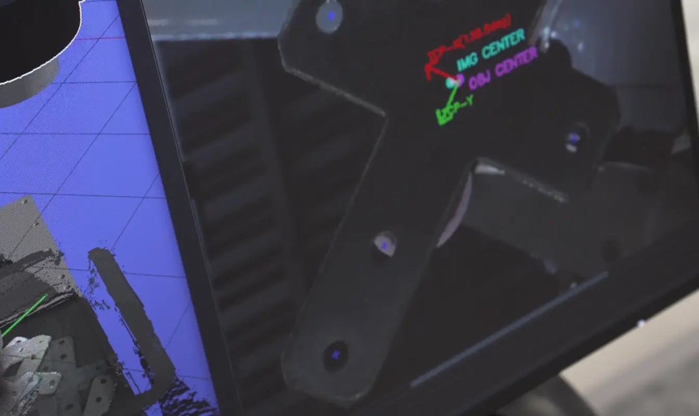
In our own systems the pick points are defined during training against the part model, then checked against neighbouring parts and bin walls by the controller before a pick is committed, which is covered in how bin picking AI models are trained. The UR5e case study shows what that looks like on a dark perforated part, where the pick points sit on solid material away from the holes so the cup always has a surface to seal against.
Validate the gripper from first contact to placement
Use the trial to check the mechanical design, including the real surface finish, contamination and part tolerances. Record failures by stage rather than reducing the result to one overall success rate.
- Reach: can the tool approach parts against the walls, in corners and at the bottom without colliding? Test a full bin and the last few parts.
- Grip: does it acquire one part reliably? Record failed seals, double picks and entangled parts, together with the available vacuum or jaw-position feedback.
- Transfer: does the part slip or rotate under the planned acceleration? Check the actual travel path and orientation changes.
- Placement: does the part arrive within the destination tolerance? If not, separate movement inside the gripper from localisation or calibration error before changing the design.
A tool that passes these checks gives you a basis for deciding whether to refine the fingers or cup, add a regrip step, or use a second tool for the remaining presentations.
Related reading: the 3D camera comparison for the other half of the decision, the bin picking field guide on cell design, and the buyer's guide on vendor selection.
Send us a bin of your parts and we return a pick video and a written verdict within 72 hours, tooling included.