Bin picking has been "almost ready for primetime" for longer than most automation engineers care to remember. The technology has matured significantly over the last decade, and today's vision-guided systems are genuinely production-capable. But the gap between a system that works and a system that works reliably in a factory environment is still wider than most vendors will tell you upfront.
We've deployed vision-based picking cells across manufacturing facilities worldwide, logging more than 30 million picks in production. What we've learned in that process forms the basis for this guide. Not what's possible under controlled conditions, but what actually happens when a bin picking system meets real factory floors, with their variable lighting, inconsistent parts, and maintenance crews who wipe down the camera housing.
The decisions that determine whether a project succeeds are rarely the obvious ones. They happen in cell design, gripper selection, integration planning, and maintenance protocols, long before and long after the robot makes its first pick. This guide covers all of them.
Is vision-guided bin picking the right solution?
The first question isn't how to implement vision-guided bin picking. It's whether to implement it at all.
Vision-guided bin picking is the right tool when parts are in random positions or orientations in a source container or when there are positional variations around a known reference position, requiring visual adjustment before picking.
If parts are arranged in a fixed, known pattern that is reliably maintained, you don't need vision. Program a fixed sequence of robot motions and let it repeat. Adding a vision system to a deterministic problem adds cost and complexity without adding value.
When other solutions are a better fit
Manually loading into a fixture makes more sense when loading time is a small fraction of the total processing time on the part. If loading a part into a welding fixture takes 5 seconds and welding takes 60, the economics of automating the load step with vision are harder to justify.
Input trays that ensure fixed and consistent part positions are preferred if the upstream process allows it. Eliminating randomness before it reaches your cell is almost always preferable to solving it there.
Bowl feeders are appropriate when you have a limited number of SKUs with small, simple, non-fragile parts. They don't scale to variety, but within their operating range, they're fast and reliable.
Early warning signs a project will struggle
Some projects show their problems before serious engineering hours are committed. Parts that are extremely difficult to recognize or grip reliably are the clearest signal. If you're already uncomfortable with the geometry at the feasibility stage, production will confirm those concerns.
Cycle time targets that don't match task complexity are another red flag. A 4-second cycle is achievable for simple parts that are pickable with suction cup grippers and that don’t require precise placing, but not for complex parts requiring precise finger positioning and high-accuracy placement.
A 100% success rate requirement is worth scrutinizing. In practice, 98–99.9% is what well-tuned production cells achieve, and designing around a theoretical ceiling creates more problems than it solves.
Applications with thousands of diverse SKUs, such as warehouse fulfillment scenarios with varying shapes, materials, and weights, are among the hardest in the industry. The technology exists, but the engineering scope and tuning time are substantially higher than single- or low-SKU manufacturing applications.
Common misconceptions from first-time users
Two misconceptions come up consistently. The first is that adapting to new SKUs is quick and straightforward. While our AI-powered approach has made it easier, it isn't always. Depending on the system and workflow, adding a new workpiece can take anywhere from minutes to days, and some scenarios require CAD data submission or paid retraining.
The second is that 100% recognition rates are achievable out of the box. Plan for a tuning period and set acceptance criteria that reflect production reality, not demo conditions.
What a bin picking system actually includes
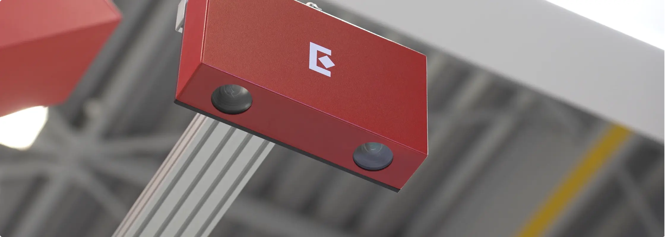
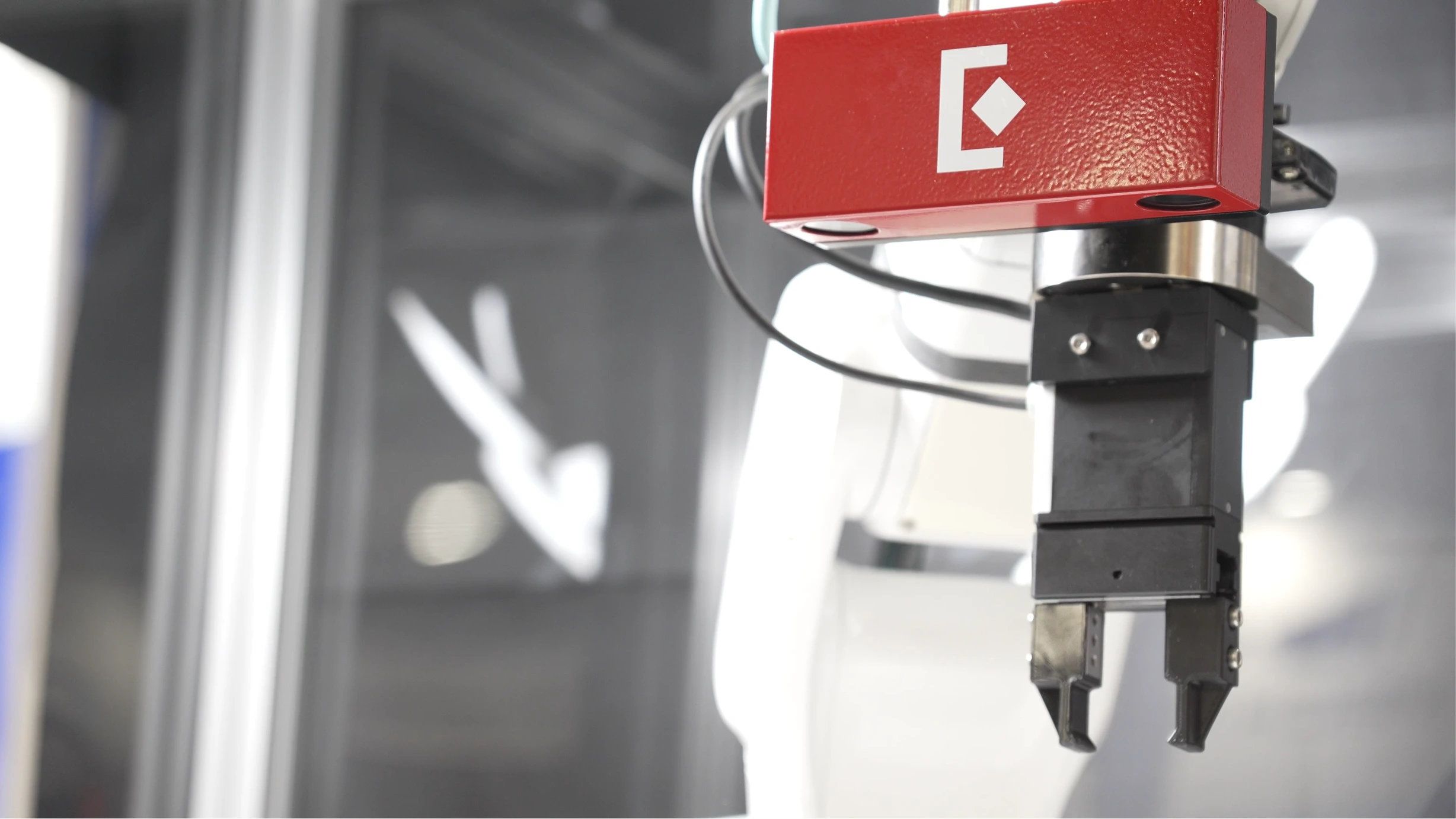
Bin picking is often described as "camera plus robot." In practice, it's more than that. A complete system includes a robot arm, a 3D camera, a controller with AI capabilities to analyze the scene and direct the pick, an end-effector, a lighting setup, a mechanical structure including a robot stand, a camera gantry, source and destination containers and gripper fingers, an electrical panel, and safety components including physical fencing or light curtains.
Our Eureka AI Vision System integrates the Eureka 3D Camera and Eureka Controller to handle the vision and decision-making side of this. But the mechanical and electrical scope is substantial and shouldn't be underestimated in project planning.
Where engineering time actually goes
Most of the engineering time in a bin picking cell goes to testing, troubleshooting edge cases, and fine-tuning on site, not necessarily to integration or software setup. This is the part of a bin picking project that is most consistently underestimated in project schedules.
Realistic deployment timeline
Expect one to two weeks of preparation off-site, covering model training, application logic development, camera and controller integration, and initial tuning.
On-site installation and production ramp-up typically take a few days to two weeks on top of that. Getting the first pick in an afternoon is realistic with the Eureka AI Vision System. Getting to stable production performance takes longer, and it's worth planning for it explicitly rather than assuming ramp-up will be fast.
Evaluating your parts and bins
Part and bin characteristics determine a large portion of what's possible before a line of code is written or a camera is mounted. The fastest way to understand your application's feasibility is to send us your parts for lab trials—a complimentary service you can request on our website. The process of developing a demo with real hardware gives both sides a reliable read on project difficulty that no desktop assessment can fully replicate.
Characteristics that make bin picking a safe bet
Matte surfaces that are clearly visible to the camera without reflections or transparency issues, parts large enough relative to the container to be localized reliably, flat smooth areas that a suction cup can seal against, and destinations that allow bulk placement without high-precision requirements.
Applications that hit all of these tend to be straightforward to tune and predictable in production.
Characteristics that add meaningful difficulty
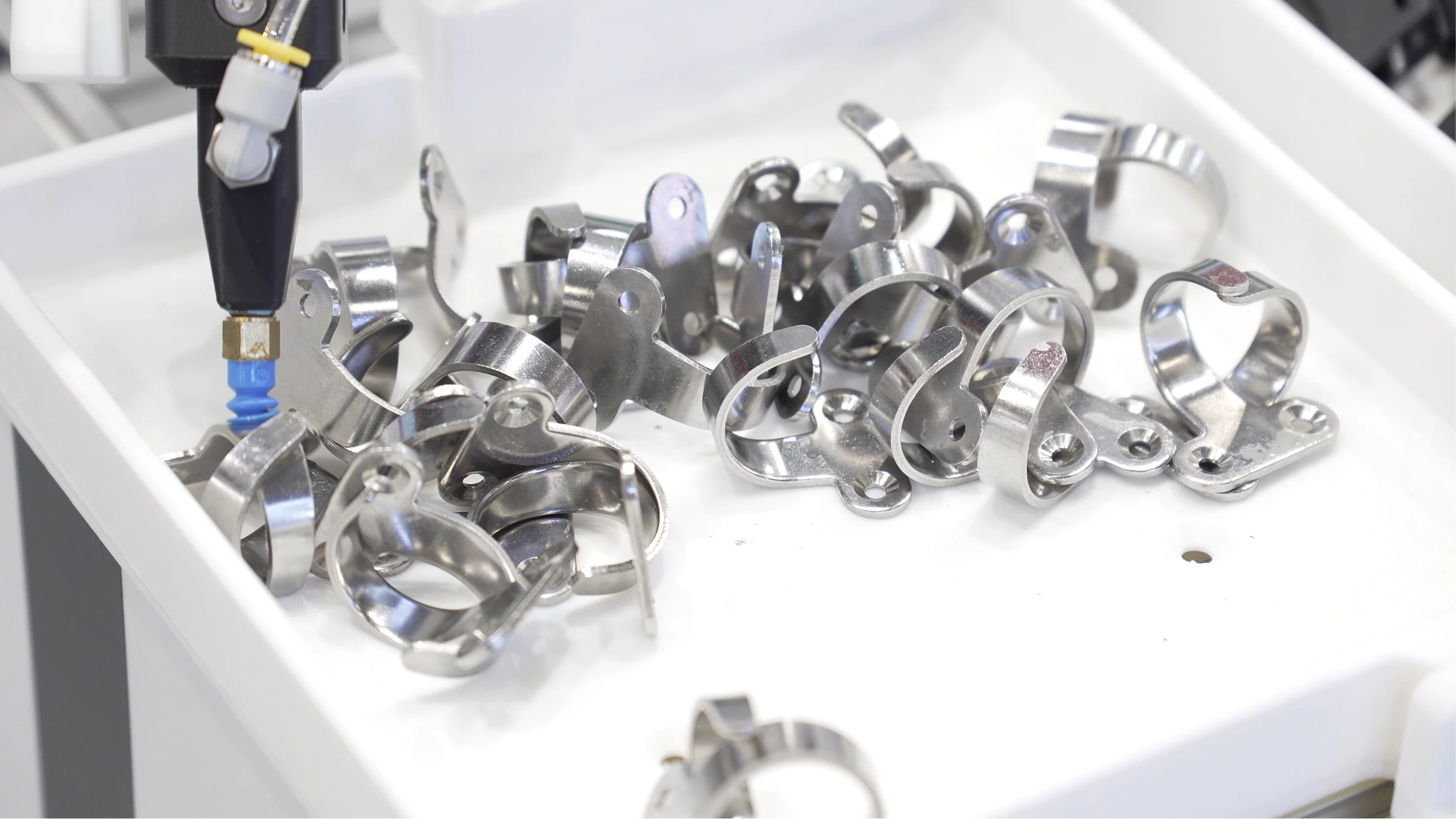
Reflective metallic surfaces, transparent or near-transparent materials, and dark objects that absorb light are consistently problematic for 3D vision (although we have made considerable progress in those areas). Irregular surfaces that neither a suction cup nor a two-finger parallel gripper can handle well require more complex end-effector design, with associated cost and mechanical fragility.
High part density relative to container size makes localization harder. Many small parts in a large bin is a substantially more difficult problem than a few large parts in the same container.
High-precision placement requirements, parts that need to be flipped between pick and place, or complex placement patterns all extend cycle time and increase engineering scope.
What to avoid entirely
Although they make for impressive demos at trade shows, fully transparent parts, such as pure glass components, are generally not viable for bin picking. Translucent parts are difficult but often workable. If your parts fall into this category, feasibility testing before project commitment is a worthwhile investment.
A note on weight and size
Both are relative rather than absolute. Size difficulty depends on the ratio of part size to container size: a 2mm part in a 10cm container is manageable, while a 2mm part in a 1-meter container is very difficult.
Weight difficulty depends on gripper type. A heavy carton box may be straightforward to pick with a large suction cup, while a heavy, small, irregularly shaped part is difficult because no standard gripper handles it well. Evaluate these factors together rather than independently.
Recap: Is your bin picking project feasible?
Understanding the vision system
You don't need to be a vision engineer to make good decisions about a bin picking system, but a working understanding of how 3D vision works helps avoid common mistakes.
A standard camera captures two dimensions, left/right and up/down, without depth information, which is insufficient for directing a robot to pick a part in 3D space. A 3D camera adds depth, giving the system the full spatial information needed to localize a part and plan a pick.
The Eureka 3D Camera uses stereo vision combined with AI-based depth reconstruction and is available in configurations for in-hand picking at 300–600 mm, standard tabletop picking at 600–1200 mm, and long-range applications at 1200–4000 mm. Choosing the right model for your working distance and container size is an important early decision.
What actually breaks detection accuracy in factories
Although our AI Vision System is comparatively robust under changing light conditions, lighting remains the most common source of problems. A section of the image might become overexposed, reflective parts might show unexpected glares, etc. because of an unplanned light source nearby; conversely, another section of the image might become underexposed because the bin is deep and overhead lighting doesn't reach the bottom.
These problems are manageable with thoughtful cell design but appear in factories far more often than in development environments, and they're worth designing around proactively rather than solving reactively.
Calibration: where errors actually appear
Two types of calibration matter. Camera intrinsic calibration is done at our manufacturing facility and rarely needs revisiting by the end user.
Camera-to-robot calibration is where practical errors appear in the field. Common mistakes include wrong definition of the tool reference frame or camera reference frame, insufficient variability or coverage in the calibration poses, etc. A careful understanding of the basic ideas behind calibration is required, and Eureka engineers are always here to help.
Accuracy: what to realistically expect
A practical rule of thumb is to expect approximately 0.5% of container size for end-to-end system accuracy. For a 10cm tray, that's around 0.5mm; for an 80cm bin, around 4mm.
Design placement requirements around realistic accuracy rather than theoretical minimums.
Cell design decisions
Good cell design has more impact on cycle time and pick success rate than almost any software tuning decision, and getting it right before installation is substantially easier than correcting it afterward.
Camera placement
In most applications, mount the camera in a fixed location above the source bin. The correct distance depends on bin size, part size, camera model, and robot size (to avoid the robot hitting the camera during motion).
An in-hand camera, mounted on the robot wrist rather than a fixed gantry, is worth considering when multiple bins need coverage, when parts are small and require close-up inspection, or when parts may be in unpredictable positions across a large area. Be aware that in-hand cameras add 1–2 seconds to cycle time because the robot must stop above the part before capturing. Fixed cameras allow continuous robot motion with image capture happening between picks, which is an important difference at scale.

Gripper selection
Suction cups are the preferred option when the part has a large enough, flat, smooth, uncontaminated surface to seal against. They're mechanically simpler and faster, because cup orientation relative to the part matters less.
Use a two-finger parallel gripper when suction isn't viable. It's the most mechanically robust finger gripper design available. More complex designs, such as four-finger grippers, exist for unusual geometries but add mechanical complexity and potential failure points. As a general rule, finger grippers add 1 to 2 seconds to cycle time compared to suction cups.
What drives cycle time
The main variables are camera configuration, gripper type, and robot type. Fixed cameras are 1–2 seconds faster than in-hand. Suction cups are roughly 1–2 seconds faster than finger grippers. Industrial robots are 3–4 seconds faster than cobots, which are speed-limited by design.
These choices compound. A cell with an in-hand camera, a finger gripper, and a cobot will have substantially longer cycle times than one with a fixed camera, a suction cup, and an industrial robot.
Realistic targets for well-designed cells are approximately 5 seconds for simple parts picked by suction cup and placed in bulk and 7–8 seconds for complex parts requiring precise finger positioning and accurate placement.
The most important design principle
When a problem has two potential solutions, one mechanical and one software-based, choose the mechanical solution. Software can compensate for a great deal, but rarely as reliably or as cost-effectively as addressing the physical setup directly.
Integration realities
This is the part of a bin picking project that rarely appears in vendor presentations, but it's where most delays actually originate.
The most common integration bottlenecks
Outdated robot or PLC software tops the list. Proprietary, developer-unfriendly interfaces that require workarounds add days to timelines that were already tight. Like most controllers, the Eureka Controller is designed to work best with updated, open robot and PLC architecture and standard communication protocols, such as EtherNet/IP, TCP/IP, or Modbus. If your robot platform has a reputation for closed APIs, budget additional time accordingly.
Network configuration problems also appear repeatedly: underpowered switches, WiFi congestion, and latency issues that don't surface until the system is under production load. Use wired CAT6 or better throughout and avoid WiFi communication between cell components wherever possible.
Realistic engineering budgets for system integrators
A realistic budget for a standard cell is one week for mechanical design and assembly (with 4–6 weeks of fabrication lead time), one week for electrical design and testing (same lead time), and a few days to two weeks for on-site installation, testing, and ramp-up, typically done with a Eureka engineer present to support.
These reflect what experienced integrators with relevant cell experience actually spend, not conservative estimates padded for uncertainty.
Performance expectations
What to expect in production
In production, expect cycle times of 4–8 seconds and pick success rates of 98–99.9%. These are consistent with what we observe across deployed cells.
Lab demos often don't push cycle time aggressively, so production performance sometimes exceeds the demo. Success rates also tend to improve from demo to production as more tuning time is invested before go-live.
The reliability metrics that actually matter
Three things matter over the life of a system: pick success rate, system downtime for debugging and fixes, and system downtime to add new SKUs.
The last one is frequently overlooked in initial evaluation but becomes significant as the system matures. Systems that require vendor involvement or CAD submission to add new workpieces create operational dependencies that compound over time. Our systems allow customers to train similar workpieces independently, without expensive engineering support, which matters for the long-term ROI of the system.
Failure modes and lessons learned
The most common post-go-live failures
Mechanical failure of the gripper, cables and connections loosening due to repetitive robot motion, and camera-to-robot calibration drift caused by vibration or physical shock to the camera mount are the failures we see most consistently.
Calibration drift is particularly insidious because it doesn't cause immediate, obvious failures. Instead, it produces a gradual increase in placement errors or intermittent failures that are difficult to reproduce. If miss rates increase over weeks or months, recalibrate before assuming a software problem.
The hardest problems we've encountered
Among the more difficult issues we've debugged: a cleaning crew wiped the camera housing, shifting it by less than 0.1 degrees. Because the camera was mounted more than 1 meter above the source bin, this produced approximately 1 mm of localization error and a placement failure roughly once every few hundred cycles (the robot was picking laser lenses and needed to place them into coating jigs with very tight clearance).
The failure was rare enough to resist easy reproduction, and the cause wasn't obvious because nobody considered that the camera had been touched. The practical lesson: write a clear maintenance SOP specifying what staff can and cannot do near the camera, and include camera inspection in any routine maintenance checklist.
Preventive steps that pay for themselves
A clear cell maintenance SOP, quarterly preventive maintenance visits, and multi-day stress testing before delivery or go-live are consistently the difference between cells that run reliably for years and cells that generate ongoing support calls.
None of these are novel recommendations, but they're the ones most often skipped when schedules are tight.
What we tell every customer
Even with a well-engineered system, unforeseen issues arise on the production floor. That's not a failure of the technology. It's the nature of deploying any system into a complex, variable environment.
What determines project success more than any technical factor is having a customer-side point of contact who understands both the production process and the realistic capabilities of AI and robotics systems, and who is committed to working through issues collaboratively. Projects that struggle usually involve a handoff mentality. Projects that succeed involve shared ownership.
ROI and financial justification
The simplest rule of thumb: if the system frees up one worker across two shifts per day, it's likely worth investigating further. More precisely, the economics depend on part value. High-value parts may justify a system at a few hundred picks per day; low-value parts like small injection-molded plastics typically require a few thousand.
These are reasonable starting points for an initial assessment, not substitutes for project-specific analysis.
Where cost is consistently underestimated
Hardware cost is visible and easy to quote. Engineering time to get a complex system to stable production performance is less visible and more variable, and it's where budget surprises most often occur.
Installation, testing, and ramp-up labor is the line item teams most consistently underestimate, particularly for complex systems.
Payback period
In the US market, 2–4 years is a reasonable rule of thumb for a well-scoped project. Applications with tight cycle time requirements, difficult parts, or frequent SKU changes tend toward the longer end.
Before you commit: a pre-project checklist
Information to gather upfront
For workpieces: images of the parts, CAD data if available, total number of SKUs in rotation, and how frequently new SKUs are introduced.
For the source bin: images of the bin empty and loaded, whether parts are fully random in 3D or have some structure, and which faces are typically oriented upward.
For the destination: images of the target bin or jig, required placement accuracy, and whether the destination position is fixed or variable.
Operationally: required cycle time, expected ROI targets, gripper constraints including designated or excluded gripping positions, and any safety or environmental requirements including interaction with human operators.
What to prototype before committing
We typically recommend a picking demo in our lab with the customer's actual parts. Building that demo with real hardware surfaces surprises early, when they're cheapest to address, and produces enough information for a realistic project proposal.
If the part is unique, it's a better investment than a desktop feasibility assessment, and it gives both sides a shared understanding of the application that's difficult to develop any other way.
If you’re interested in testing your application, please don’t hesitate to contact us.
What separates projects that succeed from those that struggle
On the customer side, it comes down to one thing: the person or team leading the project needs to understand both the production process and the realistic capabilities and limitations of AI and robotics systems.
Technical sophistication without production knowledge isn't sufficient. Production knowledge without realistic technology expectations isn't either. When those two things come together, projects succeed. When they don't, even good technology has a harder time delivering results.
Closing words
Most of what's in this guide was learned the hard way, across numerous deployments and more than 30 million production picks. We employ some of the leading vision and AI engineers in the field, and we've built systems for some of the most demanding production environments in the world, including facilities run by Pratt & Whitney, Coherent, Sumitomo Bakelite, or Maruwa Electric & Chemical.
If you're working on a bin picking application and want to understand what's feasible for your specific parts and process, a lab demo with your actual part is the best place to start. It's how we work, and it's consistently the fastest path to a realistic project proposal. Get in touch.